Asset tracking and vehicular telemetry require balancing orbital radio signal reception against strict power constraints and counter-surveillance detection risks. Today’s tracking modules integrate multi-constellation GNSS receivers with low-power cellular protocols and intelligent motion algorithms.
1. Positioning Engine Architecture: Multi-Constellation GNSS
Early tracking modules relied solely on the US NAVSTAR GPS L1 band at 1575.42 MHz. In dense urban canyons or underneath a vehicle chassis, line-of-sight satellite reception drops below usable signal thresholds (often under -145 dBm).
Contemporary telemetry hardware combines multi-band receivers capable of capturing signals across multiple sovereign constellations simultaneously:
- US GPS (L1 C/A & L5): The L5 civilian band provides higher transmission power and advanced multi-path rejection, allowing receivers to ignore reflections bouncing off wet asphalt or concrete walls.
- European Galileo (E1 & E5a): Provides superior geometric accuracy and rapid ionospheric correction calculation.
- GLONASS & BeiDou: Increases total available satellite vehicles in high-latitude environments, securing rapid geometric fixes (dilution of precision < 1.2).
2. Energy Budgets & Sleep Scheduling Mechanics
Because physical deployment on targets of interest precludes frequent battery replacement, tracking units rely on extreme power conservation. A continuous GPS fix and active cellular data socket consumes between 60 mA and 140 mA, depleting a standard lithium cell in under 48 hours.
To achieve lifespans exceeding twelve to eighteen months, devices utilize internal three-axis micro-accelerometers paired with deep-sleep firmware cycles:
| Operational State | Subsystems Active | Current Draw | RF Footprint |
|---|---|---|---|
| Deep Hibernate | Accelerometer Interrupt only | 1.8 µA | Zero RF emissions (completely inert) |
| Motion Wakeup | CPU + Ephemeris calculation | 8 mA | Zero RF emissions (passive processing) |
| Satellite Acquisition | GNSS L1/L5 Receiver active | 22 mA | Passive reception only (zero transmit RF) |
| Telemetry Burst | LTE-M Uplink Modem active | 120 mA (for 1.2 seconds) | Short pulsed cellular packet burst |
3. Passive Data Loggers vs. Real-Time Telemetry
Operational security planners distinguish between live telemetry nodes and autonomous data loggers:
Autonomous Data Loggers: These devices have no radio transmitter. They record raw NMEA positioning sentences directly to onboard NAND flash memory. Because they emit no cellular, Wi-Fi, or radio transmissions, they are immune to real-time RF sweeps. However, retrieving the intelligence requires physical recovery of the device, creating substantial operational exposure during retrieval operations.
Real-Time Uplink Modems: These units utilize low-power narrowband IoT channels (LTE-M or NB-IoT) to upload geocoordinates to an offshore command server. By queueing coordinates during highway transit and transmitting them only when moving at speeds above 60 km/h, the device ensures that any cellular transmission occurs far away from known physical sweep checkpoints or private garages.
4. Physical Deployment: Under-Chassis Geometry & Magnetics
Vehicular deployments present severe environmental stressors: high road-surface temperatures, direct water and salt wash, and severe vibrational shock. Covert tracking chassis feature IP67 or IP68 hermetically sealed polycarbonate enclosures fitted with neodymium magnet assemblies generating pull forces exceeding 45 kilograms.
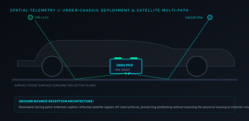
Placement requires placing the antenna facing toward the ground beneath the chassis. The antenna captures satellite signals bouncing off the road surface (ground reflection reception), insulating the unit from direct visual discovery while preserving positional telemetry fixes.
5. Vehicle Sweep Methodologies & Detection Profiles
Vehicle Inspection Points
- Inside rear bumper plastic fascias and wheel arch liners.
- Tucked above spare tire mounting brackets and heat shields.
- Parasitic splices into the 12V OBD-II diagnostic port harness.
- Concealed within engine compartment auxiliary fuse boxes.
Detection Challenges
- Motion-sensor units remain RF-silent whenever the car is parked.
- Automobile metal frames shield transmissions from external directional antennas.
- Automotive ECUs and radar sensors create heavy electromagnetic background noise.
6. Verification and Inspection Summary
A vehicle sweep cannot rely solely on RF detectors while the vehicle is parked. A certified vehicle audit requires putting the vehicle on a hydraulic lift for complete physical visual and tactile sweeps, conducting NLJD sweeps over plastic panels and frame cavities, and monitoring RF telemetry emissions while the vehicle is driven under real-world operating conditions.