Acoustic interception systems represent one of the oldest yet most technically refined disciplines within tactical signals intelligence. Contemporary audio monitoring hardware has transitioned from simple analog oscillator circuits to agile, digital burst-transmitting systems and cellular-integrated listen-in nodes.
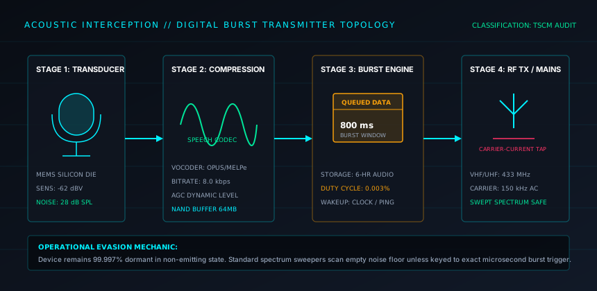
1. Acoustic Transducer Technologies: Electret vs. MEMS
Every audio interception device relies on an input transducer to convert minute atmospheric air pressure oscillations into an electrical audio voltage. Two primary architectures dominate current covert audio hardware:
- Subminiature Electret Condenser Microphones (ECM): Traditionally sized between 3 mm and 6 mm, ECMs utilize a permanently charged fluorocarbon diaphragm. They exhibit superior signal-to-noise ratios (SNR exceeding 65 dB) and excellent wide-band frequency response (20 Hz to 20 kHz), allowing operators to capture whisper-level conversation across an entire boardroom.
- Silicon Micro-Electro-Mechanical Systems (MEMS): Etched directly into silicon wafers, MEMS microphones measure less than 2x2 mm and are surface-mounted onto circuit boards. Their mechanical rigidity provides extreme resistance to physical shock, temperature fluctuation, and electromagnetic interference, making them virtually impossible to detect with standard acoustic tap-tests.
2. Radio Frequency Transmission Topologies
Once audio is captured and amplified, it must be relayed to an extraction post. The selection of transmission topology determines both the operational range and the ease with which technical surveillance counter-measures (TSCM) can detect the device:
| Transmitter Class | Modulation Type | Detection Difficulty | Power Autonomy |
|---|---|---|---|
| Continuous Narrowband VHF/UHF | NBFM (12.5 kHz Channel) | Low (Immediate detection via sweeping receiver) | 24–72 hours on coin cell |
| Direct Sequence Spread Spectrum (DSSS) | Spread Spectrum (Chirp / Pseudo-Noise) | High (Signal appears below background noise floor) | 12–36 hours on battery pack |
| Digital Burst Transmitter | Fast GFSK compressed package | Extremely High (Transmits milliseconds per hour) | Several months on LiSOCl2 battery |
| GSM / 4G Cellular Interface | Cellular Voice / Encrypted VoIP Uplink | Moderate (Emits typical cellular handshake signatures) | Continuous when wired to building mains |
3. Digital Burst Transmitters: Evasion by Design
In high-threat environments, continuous radio transmission is suicidal for an operation. Dedicated TSCM sweep teams utilize high-speed spectrum analyzers that flag any persistent radio frequency peak within seconds. To counter this, advanced audio bugs employ memory buffers and digital compression engines.
The bug records ambient audio continuously, digitizing the signal with a speech-optimized codec (such as Speex or Opus at bitrates as low as 8 kbps). The audio remains stored in flash memory. At predetermined time windows (e.g., at 03:00 hours) or upon receiving an encrypted interrogator ping from an external receiver, the device compresses hours of accumulated recording into a high-speed data burst lasting less than 800 milliseconds. Standard sweep detectors scanning through RF bands will miss the transmission entirely unless synchronized to the exact microsecond and carrier frequency.
4. Parasitic Mains Integration and Carrier-Current Vectors
Battery depletion is the principal limitation of covert audio installations. To achieve indefinite operational lifespans, transceivers are routinely integrated into electrical infrastructure: wall sockets, power distribution strips, ceiling lighting fixtures, and circuit breaker panels.
Beyond using building mains purely for AC-to-DC rectification, specialized transmitters utilize carrier-current transmission. Instead of broadcasting radio waves into free space via an antenna, the device injects high-frequency RF signals (typically between 50 kHz and 5 MHz) directly onto the copper AC electrical wiring. The building's copper grid functions as a closed transmission conduit. The signal travels along the electrical wiring out to the local step-down power transformer, where a listening post plugged into the same power loop can decode the audio stream without emitting a single watt of over-the-air radio radiation.
5. Vulnerability Profiles & Mitigation Strategies
Detection Signatures
- VHF/UHF analog carriers produce unmistakable spike signatures on waterfall spectrum displays.
- Parasitic power supplies emit characteristic 50/60 Hz mains harmonic hum on unshielded audio preamps.
- GSM modules generate high-peak TDMA buzz in nearby passive speaker coils during cell handshakes.
Defensive Countermeasures
- Deploying pink-noise acoustic generators against perimeter drywall and glass partitions.
- Installing broad-spectrum power line filters at breaker junction points to block carrier currents.
- Utilizing non-linear junction detectors (NLJDs) to locate semiconductor diodes in inert or sleeping bugs.
6. Acoustic Engineering Assessment Summary
Defending against modern acoustic bugs requires recognizing that RF silence does not guarantee acoustic privacy. Modern audits must combine RF spectrum monitoring with high-frequency mains line testing, broadband non-linear junction sweeps, and acoustic isolation protocols within conference facilities.