Modern optical surveillance relies on reducing the physical point of exposure to microscopic tolerances. While standard CCTV systems display visible dome glass and large entrance pupils, covert optics utilize conical pinhole lenses that require an aperture opening as narrow as 0.8 millimeters to deliver wide-angle visual records.
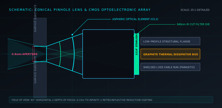
1. Conical Pinhole Lens Geometries
The fundamental component of an integrated covert camera is the pinhole objective lens. Standard industrial lenses utilize front diameters matching their barrel width, but a specialized pinhole optic uses an inverted cone geometry. The external tip of the cone narrows down to a micro-diameter, allowing the assembly to sit recessed behind architectural surfaces, screws, smoke detectors, electrical outlets, or picture frames.
Achieving adequate exposure through a sub-millimeter portal presents severe optical trade-offs. The light gathering power (measured by f-number) degrades rapidly as the physical aperture decreases. Most pinhole lenses operate between f/2.0 and f/2.8. At this aperture, maintaining image quality demands high quantum efficiency from the underlying CMOS sensor, frequently necessitating back-illuminated pixel architectures to capture sufficient photons in dimly lit conference rooms or residential settings.
2. Sensor Thermal Management and Enclosure Dissipation
A common vulnerability of disguised video capture modules is thermal accumulation. Video processing engines that compress uncompressed pixel data into H.264 or H.265 streams generate consistent heat ranging from 1.5 to 3.5 watts. In a standard chassis, cooling occurs through passive convection fins. In a covert deployment—where the sensor and SoC are embedded within drywall, inside faux appliances, or insulated enclosures—heat cannot circulate freely.
Thermal buildup results in two catastrophic failure modes:
- Sensor Noise Saturation: As silicon temperature rises above 55°C, thermal dark current generates substantial fixed-pattern noise, blooming, and chromatic distortion across low-light frames.
- Thermal Signature Exposure: Counter-surveillance sweeps routinely employ forward-looking infrared (FLIR) radiometric imagers. A concealed module operating inside a drywall cavity produces a localized 10°C to 15°C thermal delta on the wall surface, immediately compromising the installation to passive thermal inspection.
3. Physical Integration Categories & Spectral Bands
Engineers categorize covert video systems based on their transmission architecture and illumination spectrum:
| Category | Transmission Path | Power Supply | TSCM Vulnerability Profile |
|---|---|---|---|
| Hardwired Micro-Coax | Analog HD / LVDS Shielded Cable | Direct 12V DC Mains | Immune to RF sweeps; detected via cable tracers and NLJD. |
| Local Storage Micro-SD | Zero RF (Autonomous Logging) | High-density Li-Ion cell | Undetectable by RF analyzers; identified by optical retro-reflection. |
| Wi-Fi / Cellular Streamer | 2.4/5.8 GHz or LTE Cat-M1 | Parasitic draw from AC load | High RF footprint; vulnerable to spectrum analyzers and Wi-Fi sniffer beacons. |
4. Illumination: 850 nm vs. 940 nm Covert Bands
When ambient illumination falls below 0.01 lux, sensors require active infrared illumination. Standard security infrared diodes emit light at 850 nanometers. While invisible to the human eye in beam form, the diode chip exhibits a dull red glow visible in pitch darkness. For covert operations, illuminator arrays must strictly use 940 nanometer emitters. These emit no visible red glow whatsoever. However, standard silicon CMOS sensors suffer a 40% to 60% loss in sensitivity at 940 nm compared to 850 nm, demanding either higher LED emitter density or larger sensor pixel pitch.
5. Advantages and Operational Trade-Offs
Operational Strengths
- Visual recording through openings under 1 mm in diameter.
- High-resolution 1080p and 4K digital detail from recessed positions.
- Flexible integration behind common everyday building materials.
- Autonomous continuous operation when integrated into primary power lines.
Systemic Vulnerabilities
- Optical glint easily identified by handheld laser lens locators.
- Localized thermal hot spots reveal location to thermal cameras.
- Fixed focal length prevents dynamic depth reframing after installation.
- Lens obstruction caused by surface dust accumulation over prolonged deployments.
6. Selection & Verification Criteria
When architecting an inspection sweep or specifying covert recording equipment, verify the sensor’s native dynamic range (minimum 100 dB WDR is recommended to prevent blinding from open windows), verify whether the casing incorporates graphite heat pipes to distribute thermal energy over larger surface areas, and audit the enclosure using a retro-reflective optical sweep to assess external glint exposure.